This blog post gives a deeper understanding of a voltage divider, more precisely a resistive voltage divider. Based on two resistors connected in series, typical use cases are the creation of a reference voltage or a voltage reduction to measure it.
Table of Content
First, the blog post explains a generic voltage divider (cf. Introduction), followed by the description of a resistive divider (cf. Resistor-based Voltage Divider). Based on the described equation of a resistive divider, the blog post calculates an output voltage (cf. Exemplary Calculation) and proofs the stated equation of a resistive divider (cf. Proof of Equation). Afterwards, the blog post explains a resistive divider under load (cf. Behavior Under Load) and finally concludes (cf. Conclusion).
Introduction
A voltage divider is a passive linear circuit. It consists of two passive components, connected in series. Due to the connection in series of the two components, the output voltage is a fraction of the input voltage. The division of the input voltage results from its distribution among the two components. Depending on the use case, the two components are typically any combination of resistors, inductors, and capacitors. Most common, the two components are resistors, resulting in a resistive divider. Also common as a voltage divider are the combination of a resistor and a capacitor (low-pass RC filter), two inductors (inductive divider), or two capacitors (capacitive divider).
Resistor-based Voltage Divider
The typical voltage divider is a circuit with two resistors, connected in series. A common use case of such a resistive divider is the creation of a reference voltage or the reduction of the input voltage for measurements. The created output voltage depends upon the existence of a load (cf. Behavior Under Load) or the non-existence of a load, named open circuit behavior, explained below:
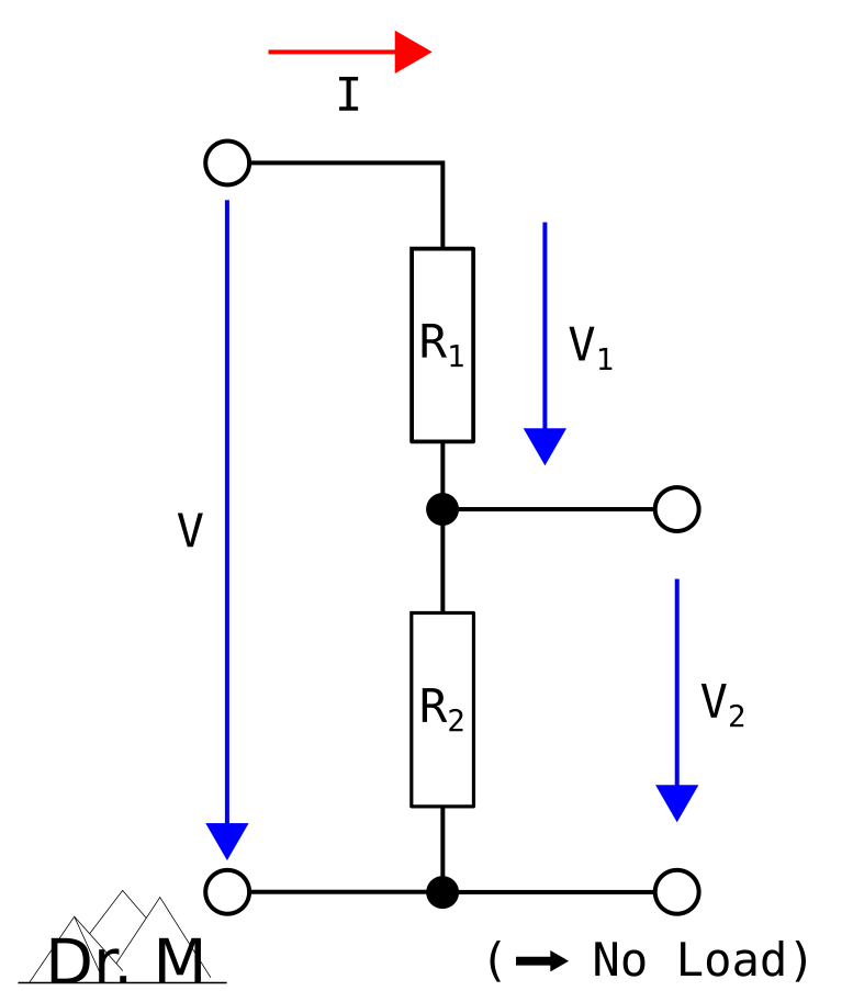
Open Circuit Behavior
Knowing the resistance R1 and R2 of the two resistors, the output voltage V2 is:
(1) 
and, likewise, for the output voltage V1:
(2) 
Exemplary Calculation
The following figure shows an exemplary voltage divider based on two resistors, connected in series:
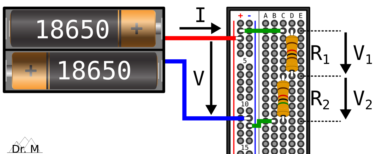
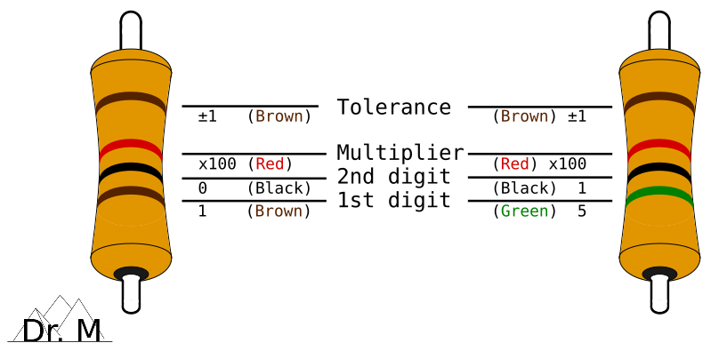
The resistance of the four-band resistor R1 is 1k Ohms with a tolerance of ±1% and the resistance of the four-band resistor R2 is 5k Ohms with a tolerance of ±1%. For instance, use the following calculator for the color code of resistors:
Moreover, the battery-based power supply delivers an input voltage of 8.4 volts (VTotal) due to two fully-charged LiPo batteries (read more about a LiPo-based power supply for the ESP32-CAM here). Now, let’s calculate the output voltage:
(3) 
Proof of Equation
To proof Equation (1) stated above, let’s start with Ohm’s Law, and especially for the second resistor R2:
(4) 
Based on the series connection of the resistors, the current flowing through the circuit is constant (I = ITotal = I1 = I2) and the total overall resistance of the circuit is RTotal = R1 + R2 (cf. behavior of series circuits):
(5) 
(6) 
Now, let’s combine Equation (3) and Equation (4):
(7) 
That’s it, QED!
Behavior Under Load
In case the output voltage V2 depends upon the existence of a load RL, the circuit of a resistive divider changes from a series connection to a series and parallel connection. The load adds to the two resistors R1 and R2 another resistance RL, connected in parallel to the resistance R2 (R2 || RL). Thus, the series connection under load extends to R1 + (R2 || RL):
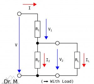
Behavior Under Load
Due to the load added, the total overall resistance RTotal of the circuit decreases:
(8) 
and the total overall current ITotal flowing through the circuit increases:
(9) 
resulting in an increase of the voltage V1 and a decrease of the voltage V2 . To calculate the output voltage V2 of a resistive voltage divider under load, we first define a forward slope resistance R2L and set it in Equation (1):
(10) 
(11) 
In order that the load RL has as less effect as possible on the output voltage V2, the resistance R1 and R2 should be considerably smaller than the load RL:
(12) 
Conclusion
A resistive voltage divider is a passive linear circuit, consisting of two resistors connected in series. Due to the distribution of the input voltage among the two resistors (series connection), the output voltage is a fraction of the input voltage:
(13)
Release Notes:
- [2021-08-19] Initial release of the blog post comprising the description of the resistor-based voltage divider without a load (open circuit behavior), an exemplary calculation of an output voltage, and the proof of the equation
- [2021-09-11] Update of the blog post adding the description of the resistor-based voltage divider under load (behavior under load)
Neueste Kommentare