The Doc whom IoT Professionals trust

Kategorie: Power Supply

Power up the ESP32-CAM on the Input Voltage Pin 5V

Reading Time: 2 Minutes

This blog post explains the easiest way of powering up the ESP32-CAM board: Connecting an external power supply to the input voltage pin 5V on the board.

On the ESP32-CAM board, the soldered voltage regulator AMS1117-3.3 (read more about the AMS1117-3.3 here) regulates the voltage connected on the input voltage pin 5V. It delivers an output voltage of 3.3 volts and a maximum current of 1.5 amperes. To this end, the voltage regulator requires an input voltage greater than 4.5 volts due to a dropout voltage of 1 volt. In detail, both a laboratory power supply or a battery-based power supply can deliver the required input voltage.

Laboratory Power Supply

The function of a laboratory power supply is to supply a constant voltage (typically indicated by „C.V.“) or a constant current (typically indicated by „C.C.“). It converts an unregulated alternating current (AC) into a constant direct current (DC). Usually, a laboratory power supply delivers a variety of continuous or preset voltages (read more about regulated power supply on Wikipedia).

Now, it is time to power up the ESP32-CAM board with a laboratory power supply that delivers the constant voltage required:

  1. Set the output voltage of the laboratory power supply to a fixed voltage between 5 volts and 6 volts
  2. Connect the output voltage of the power supply to a ground pin GND and the input voltage pin 5V
  3. Turn on the voltage supply of the laboratory power supply to provide the required input voltage of greater than 4.5 volts to the AMS1117-3.3

That’s it. The external power supply together with the AMS1117-3.3 power up the ESP32-CAM board.

Battery-based Power Supply

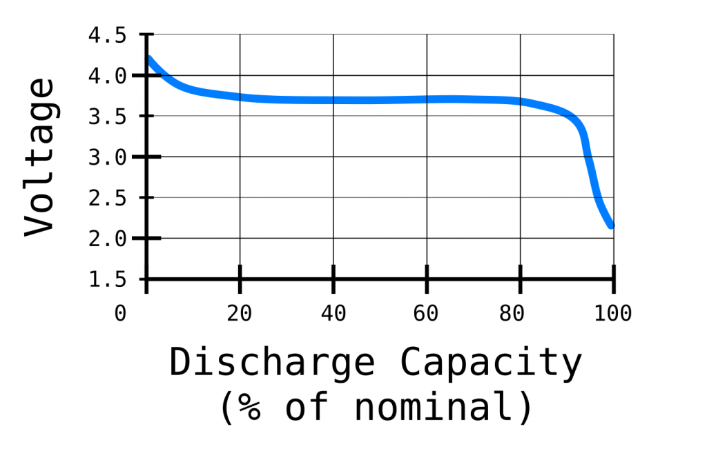
A battery-based power supply delivers an output voltage, depending on the type of the battery. For instance, a Lithium-Ion Polymer (LiPo) battery delivers an output voltage of 4.2 volt, if it is fully-charged. While discharging, the supplied output voltage decreases to 3.7 volts. Please note that the output voltage of a LiPo battery should not reach 2.5 volts or less – better 3 volts or less. Otherwise, it could permanently damage the LiPo battery:

Typical Voltage Discharging Curve of a Lithium-Ion Polymer Battery

Due to the required input voltage of greater than 4.5 volts, the number of needed LiPo batteries is two LiPo batteries connected in series:

Battery-based Power Supply by 2 LiPos of ESP32-CAM board

In detail, two fully-charged LiPo batteries connected in series supply an output voltage of 8.4 volts to the AMS1117-3.3, powering up the ESP32-CAM board. While discharging, the two LiPo batteries supply an output voltage of 7.4 volts, decreasing to an output voltage of 5 volts. To prevent the two LiPo batteries from a permanently damage, completely disconnect the two LiPo batteries from the electrical circuit, latest reaching the critical low voltage of 5 volts – better 6 volts.
Power up the ESP32-CAM

Reading Time: 3 Minutes

Now, it is time to power the ESP32-CAM board and get the hands-on it. This blog post gives an understanding of the possible power supplies of the board. In total, the board has two different options for power supply: Either an unregulated power to the ground pin GND and the input voltage pin 5V or a regulated power to the ground pin GND and the input voltage pin 3V3. Or jump directly to the conclusion.

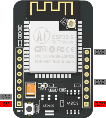
ESP32-CAM: Front-View
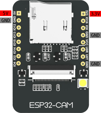
ESP32-CAM: Back-View

First Option: Connecting an external unregulated power supply (up to 15 Volt) to the ground pin and the input voltage pin 5 Volt

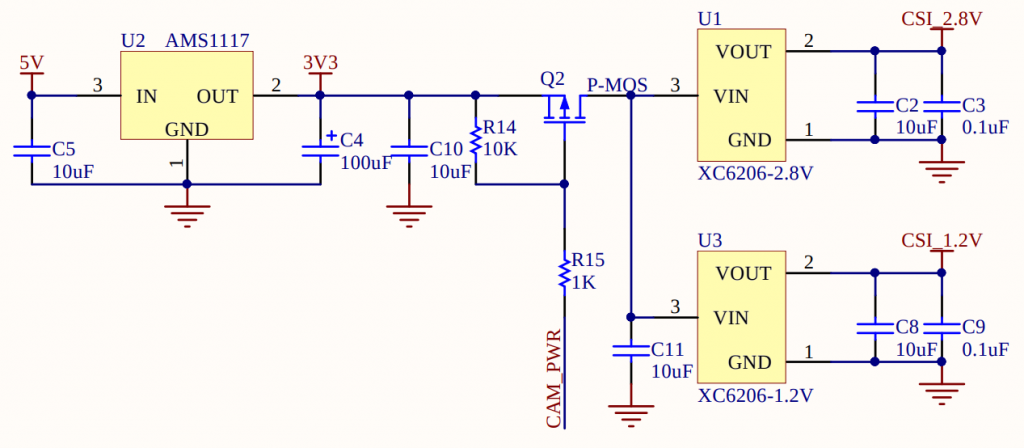
The ESP32-CAM board has a linear, Low-DropOut (LDO) voltage regulator – more precisely, the AMS1117-3.3 (read more about the AMS1117-3.3 here). It provides an output voltage of 3.3 Volt by a maximum output current of 1.5 Ampere and a maximum input voltage of 15 Volt. At the maximum output current of 1.5 Ampere, the ASM1117-3.3 operates with a dropout voltage (input-to-output differential) of 1.3 Volt, decreasing down to 1 Volt at lower load currents. The output voltage of 3.3 Volt powers the different components on the ESP32-CAM like the camera, the Pseudo-Random Access Memory (PSRAM), or the Micro SD-Card:

ESP32-CAM: Schematic Diagram of the External Power Supply (source)

Due to the soldered AMS1117-3.3, the ESP32-CAM board supports on the input voltage pin 5V an external unregulated power supply between 4.5 Volt (output voltage + dropout voltage) and up to a maximum of 15 Volt. Any voltage higher than 4.5 Volt, the AMS1117-3.3 has to dissipate the excessive voltage – more precisely, the power that equals to (VIN - VOUT) * Aas heat on the voltage regulator (read more about linear voltage regulators here). So, it is best to keep the input voltage close to 5 Volt, avoiding too much loss of power as heat on the voltage regulator (not heat dissipation mounted).

Second option: Connecting an external regulated power supply of 3.3 Volt to the ground pin and the input voltage pin 3V3

The ESP32-CAM board supports the power supply by an external regulated power of 3.3 Volt, connected to the ground pin GND and the input voltage pin 3V3 (cf. front-view and back-view of ESP32-CAM). As shown above in the schematic diagram, the power supply 3V3 bypasses the on-board voltage regulator AMS1117-3.3. As a result, the ESP32-CAM board has no protection against over-voltage, damaging the soldered components on the board. Be very careful that the connected input voltage on pin 3V3 is safe and regulated between 3 Volt and 3.6 Volt (recommended operating voltage of the ESP32 is 3.3 Volt).

Conclusion

To power the ESP32-CAM board, there are two options available:

First, an external unregulated voltage between 4.5 Volt and 15 Volt connected to the ground pin GND and the input voltage pin 5V. The ESP32-CAM board regulates the supplied input voltage on-board with the soldered AMS1117-3.3 to the required input voltage of 3.3 Volt.

Second, an external regulated voltage of 3.3 Volt connected to the ground pin GND and the input voltage pin 3V3. Be careful that the supplied voltage is not higher than 3.6 Volt! Exceeding the voltage limit will cause damages of the ESP32-CAM board.

Please note that the ESP32-CAM board should only be powered by the first option (unregulated) or the second option (regulated), NEVER EVER1 at the same time! Otherwise, both power supplies at the same time will surely damage the ESP32-CAM board.


Footnote

1. Thanks to the feedback from Doug (cf. comments)

© 2024 Dr. Mountain

Theme von Anders NorénHoch ↑