The Doc whom IoT Professionals trust

Kategorie: Power Supply

Reading Time: 2 Minutes


The data sheet of the ESP32 states its electrical characteristics (cf. esp32_datasheet_en.pdf). It specifies the absolute maximum ratings and the recommended ratings of the supply voltage applied to the power supply pins (cf. Conclusion).

Absolute Maximum Ratings

The absolute maximum rating of the voltage applied to the power supply pins VDDA, VDD3P3_RTC, VDD3P3, VDD3P3_CPU, and VDD_SDIO is between a minimum voltage of -0.3 volts and a maximum voltage of 3.6 volts. Please note that a voltage below or above the absolute maximum rating may cause a permanent damage to the ESP32 chip.

SymbolParameterMinMaxUnit
VDDA, VDD3P3_RTC, VDD3P3, VDD3P3_CPU,
and VDD_SDIO
Voltage applied to power supply pins-0.33.6V
Espressif ESP32 Data Sheet (cf. Table 11)

The recommended rating of the voltage applied to the power supply pins VDDA, VDD3P3_RTC, VDD3P3, and VDD_SDIO depends on the presence of a 3.3V flash embedded (cf. Ordering Information):

  • The ESP32 chip with the ordering code ESP32-U4WDH has a 4 MB embedded flash (80 MHz). As a result, the applied voltage is between a minimum voltage of 3.0 volts and a maximum voltage of 3.6 volts with a typical voltage of 3.3 volts.
  • The ESP32 chips with the ordering codes ESP32-D0WD-V3, ESP32-D0WDQ6-V3, ESP32-D0WD, ESP32-D0WDQ6, and ESP32-S0WD have no embedded flash. As a result, the applied voltage is between a minimum voltage of 2.3 volts and a maximum voltage of 3.6 volts with a typical voltage of 3.3 volts.

Be aware in both cases that writing to eFuse, the voltage applied to the power supply pin VDD3P3_RTC should be at least 3.3 volts.

The recommended rating of the voltage applied to the power supply pin VDD3P3_CPU is between a minimum voltage of 1.8 volts and a maximum voltage of 3.6 volts with a typical voltage of 3.3 volts.

SymbolParameterMinTypMaxUnit
VDDA, VDD3P3_RTC, VDD3P3, and VDD_SDIOVoltage applied to power supply pins2.3 / 3.03.33.6V
VDD3P3_CPUVoltage applied to power supply pin1.83.33.6V
Espressif ESP32 Data Sheet (cf. Table 12)

Conclusion

The operating voltage applied to the power supply pins ranges from 1.8 / 2.3 / 3.0 volts to 3.6 volts, where the recommended voltage of the power supply is 3.3 volts. Moreover, the recommended current delivered by external power supply 500 milliampere (or even more).


Release Notes:

  • [2021-09-04] Initial release of the blog post comprising the specifications of the absolute maximum ratings and the recommended ratings of the supply voltage applied to the power supply pins.
Technical Deep-dive into Voltage Divider based on Resistors

Reading Time: 4 Minutes

This blog post gives a deeper understanding of a voltage divider, more precisely a resistive voltage divider. Based on two resistors connected in series, typical use cases are the creation of a reference voltage or a voltage reduction to measure it.

Table of Content

First, the blog post explains a generic voltage divider (cf. Introduction), followed by the description of a resistive divider (cf. Resistor-based Voltage Divider). Based on the described equation of a resistive divider, the blog post calculates an output voltage (cf. Exemplary Calculation) and proofs the stated equation of a resistive divider (cf. Proof of Equation). Afterwards, the blog post explains a resistive divider under load (cf. Behavior Under Load) and finally concludes (cf. Conclusion).


Introduction

A voltage divider is a passive linear circuit. It consists of two passive components, connected in series. Due to the connection in series of the two components, the output voltage is a fraction of the input voltage. The division of the input voltage results from its distribution among the two components. Depending on the use case, the two components are typically any combination of resistors, inductors, and capacitors. Most common, the two components are resistors, resulting in a resistive divider. Also common as a voltage divider are the combination of a resistor and a capacitor (low-pass RC filter), two inductors (inductive divider), or two capacitors (capacitive divider).

Resistor-based Voltage Divider

The typical voltage divider is a circuit with two resistors, connected in series. A common use case of such a resistive divider is the creation of a reference voltage or the reduction of the input voltage for measurements. The created output voltage depends upon the existence of a load (cf. Behavior Under Load) or the non-existence of a load, named open circuit behavior, explained below:

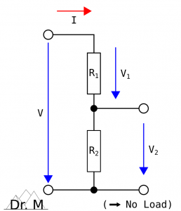
Resistor-based Voltage Divider:
Open Circuit Behavior

Knowing the resistance R1 and R2 of the two resistors, the output voltage V2 is:

(1)    \begin{equation*}  V_2 = \frac{R_2}{(R_1 + R_2)} * V_{Total} \end{equation*}

and, likewise, for the output voltage V1:

(2)    \begin{equation*}  V_1 = \frac{R_1}{(R_1 + R_2)} * V_{Total} \end{equation*}

Exemplary Calculation

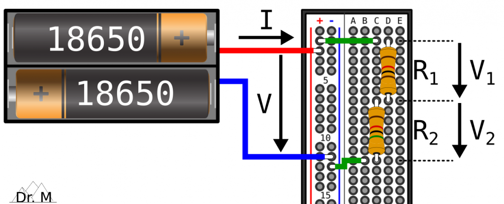
The following figure shows an exemplary voltage divider based on two resistors, connected in series:

An Exemplary Voltage Divider based on Two Resistors Connected in Series

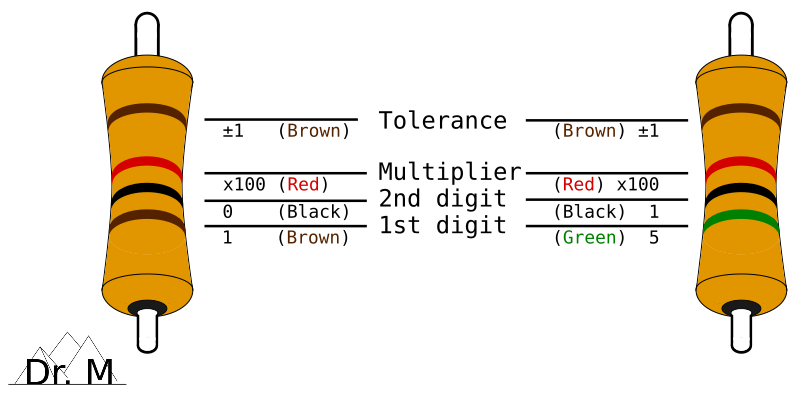
The resistance of the four-band resistor R1 is 1k Ohms with a tolerance of ±1% and the resistance of the four-band resistor R2 is 5k Ohms with a tolerance of ±1%. For instance, use the following calculator for the color code of resistors:

Moreover, the battery-based power supply delivers an input voltage of 8.4 volts (VTotal) due to two fully-charged LiPo batteries (read more about a LiPo-based power supply for the ESP32-CAM here). Now, let’s calculate the output voltage:

(3)    \begin{equation*} \begin{split} V_2 &= \frac{R_2}{(R_1 + R_2)} * V_{Total} \\ &= \frac{5000}{1000 + 5000} * 8.4 \\ &= \frac{5}{6} * 8.4 = 7 \end{split} \end{equation*}

Proof of Equation

To proof Equation (1) stated above, let’s start with Ohm’s Law, and especially for the second resistor R2:

(4)    \begin{equation*}  \begin{split} V &= R * I \\ &\Rightarrow V_2 = R_2 * I_2 \end{split} \end{equation*}

Based on the series connection of the resistors, the current flowing through the circuit is constant (I = ITotal = I1 = I2) and the total overall resistance of the circuit is RTotal = R1 + R2 (cf. behavior of series circuits):

(5)    \begin{equation*}  \begin{split} V_2 &= R_2 * I_2 = R_2 * I \\ &\Rightarrow I = \frac{V_2}{R_2} \end{split} \end{equation*}

(6)    \begin{equation*}  \begin{split} V_{Total} = R_{Total} * I_{Total} = (R_1 + R_2) * I \end{split} \end{equation*}

Now, let’s combine Equation (3) and Equation (4):

(7)    \begin{equation*}  \begin{split} V_{Total} &= (R_1 + R_2) * I \\ & = (R_1 + R_2) * \frac{V_2}{R_2} \\ & \Rightarrow V_2 = R_2 * \frac{V_{Total}}{(R_1 + R_2)} \end{split} \end{equation*}

That’s it, QED!

Behavior Under Load

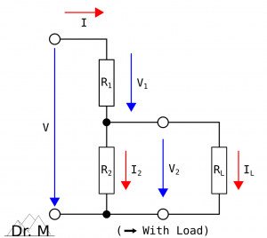
In case the output voltage V2 depends upon the existence of a load RL, the circuit of a resistive divider changes from a series connection to a series and parallel connection. The load adds to the two resistors R1 and R2 another resistance RL, connected in parallel to the resistance R2 (R2 || RL). Thus, the series connection under load extends to R1 + (R2 || RL):

Resistor-based Voltage Divider:
Behavior Under Load

Due to the load added, the total overall resistance RTotal of the circuit decreases:

(8)    \begin{equation*} \begin{split} R_{Total} &= R_1 + \frac{1}{\frac{1}{R_2} + \frac{1}{R_L}} \\ &= R_1 + \frac{R_2 * R_L}{R_2 + R_L} \end{split} \end{equation*}

and the total overall current ITotal flowing through the circuit increases:

(9)    \begin{equation*} I_{Total} = I_2 + I_L \end{equation*}

resulting in an increase of the voltage V1 and a decrease of the voltage V2 . To calculate the output voltage V2 of a resistive voltage divider under load, we first define a forward slope resistance R2L and set it in Equation (1):

(10)    \begin{equation*} R_{2L} = R_2 || R_L = \frac{R_2 * R_L}{R_2 + R_L} \end{equation*}

(11)    \begin{equation*} V_2 = \frac{R_{2L}}{R_1 + R_{2L}} * V_{Total} \end{equation*}

In order that the load RL has as less effect as possible on the output voltage V2, the resistance R1 and R2 should be considerably smaller than the load RL:

(12)    \begin{equation*}  \begin{split} R_i &= R_1 || R_2 = \frac{1}{\frac{1}{R_1} + \frac{1}{R_2}} = \frac{R_1 * R_2}{R_1 + R_2} \\ R_i &\ll R_L \Rightarrow R_i < \frac{1}{10} * R_L \end{split} \end{equation*}

Conclusion

A resistive voltage divider is a passive linear circuit, consisting of two resistors connected in series. Due to the distribution of the input voltage among the two resistors (series connection), the output voltage is a fraction of the input voltage:

(13)    \begin{equation*}  V_2 = \frac{R_2}{(R_1 + R_2)} * V_{Total} \end{equation*}


Release Notes:

  • [2021-08-19] Initial release of the blog post comprising the description of the resistor-based voltage divider without a load (open circuit behavior), an exemplary calculation of an output voltage, and the proof of the equation
  • [2021-09-11] Update of the blog post adding the description of the resistor-based voltage divider under load (behavior under load)

Power up the ESP32-CAM on the Input Voltage Pin 5V

Reading Time: 2 Minutes

This blog post explains the easiest way of powering up the ESP32-CAM board: Connecting an external power supply to the input voltage pin 5V on the board.

On the ESP32-CAM board, the soldered voltage regulator AMS1117-3.3 (read more about the AMS1117-3.3 here) regulates the voltage connected on the input voltage pin 5V. It delivers an output voltage of 3.3 volts and a maximum current of 1.5 amperes. To this end, the voltage regulator requires an input voltage greater than 4.5 volts due to a dropout voltage of 1 volt. In detail, both a laboratory power supply or a battery-based power supply can deliver the required input voltage.

Laboratory Power Supply

The function of a laboratory power supply is to supply a constant voltage (typically indicated by „C.V.“) or a constant current (typically indicated by „C.C.“). It converts an unregulated alternating current (AC) into a constant direct current (DC). Usually, a laboratory power supply delivers a variety of continuous or preset voltages (read more about regulated power supply on Wikipedia).

Now, it is time to power up the ESP32-CAM board with a laboratory power supply that delivers the constant voltage required:

  1. Set the output voltage of the laboratory power supply to a fixed voltage between 5 volts and 6 volts
  2. Connect the output voltage of the power supply to a ground pin GND and the input voltage pin 5V
  3. Turn on the voltage supply of the laboratory power supply to provide the required input voltage of greater than 4.5 volts to the AMS1117-3.3

That’s it. The external power supply together with the AMS1117-3.3 power up the ESP32-CAM board.

Battery-based Power Supply

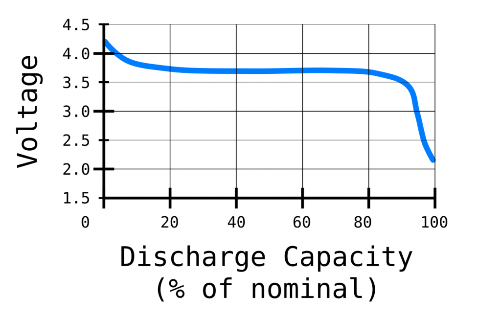
A battery-based power supply delivers an output voltage, depending on the type of the battery. For instance, a Lithium-Ion Polymer (LiPo) battery delivers an output voltage of 4.2 volt, if it is fully-charged. While discharging, the supplied output voltage decreases to 3.7 volts. Please note that the output voltage of a LiPo battery should not reach 2.5 volts or less – better 3 volts or less. Otherwise, it could permanently damage the LiPo battery:

Typical Voltage Discharging Curve of a Lithium-Ion Polymer Battery

Due to the required input voltage of greater than 4.5 volts, the number of needed LiPo batteries is two LiPo batteries connected in series:

Battery-based Power Supply by 2 LiPos of ESP32-CAM board

In detail, two fully-charged LiPo batteries connected in series supply an output voltage of 8.4 volts to the AMS1117-3.3, powering up the ESP32-CAM board. While discharging, the two LiPo batteries supply an output voltage of 7.4 volts, decreasing to an output voltage of 5 volts. To prevent the two LiPo batteries from a permanently damage, completely disconnect the two LiPo batteries from the electrical circuit, latest reaching the critical low voltage of 5 volts – better 6 volts.

Technical Deep-Dive into Linear Voltage Regulator

Reading Time: 2 Minutes

This blog post gives a deeper understanding of a linear voltage regulator. A (linear) voltage regulator plays an important role as power supply. Its main function is to automatically output a constant voltage by adjusting continuously a voltage divider network. Thus, it acts as a variable resistor, where the resistance of the regulator depends on both the input voltage and the load (cf. Ohm’s law). The voltage U in units of volts equals to the resistance R in units of ohms multiplied by the current I in units of amperes:

U = R * I

To drop some voltage on the variable resistance, the input voltage VIN of the regulator must be higher than the regulated output voltage VOUT. This difference between the input voltage and the regulated output voltage (VIN - VOUT) is called dropout voltage. The regulator has to dissipate the power loss – more precisely, the multiplication of the dropout voltage and the current drawn by the circuit – as heat. Due to the waste of energy as heat regulating the voltage, a linear voltage regulator has a limited efficiency. The heat dissipated by the regulator relates directly to the average amount of electric power dissipated by the regulator. The electric power P in units of watts equals to the voltage U in units of volts multiplied by the current I in units of amperes:

P = U * I = (VIN - VOUT) * IMAX

where VIN is the input voltage of the regulator, VOUT the regulated output voltage of the regulator powering the circuit, and IMAX the maximum current drawn by the circuit. For a safe estimation, the equation calculates the peak power with the maximum current drawn (worst-case scenario), not continuously draw by the circuit. Thus, the regulator has to dissipate more heat (power loss) as, on the one hand, the difference of the input voltage and the regulated output voltage gets greater, and/or, on the other hand, the current drawn gets greater. To expose more heat from a regulator under load, a heat sink with „fins“ increases the surface area of the regulator, cooling it more efficiently.

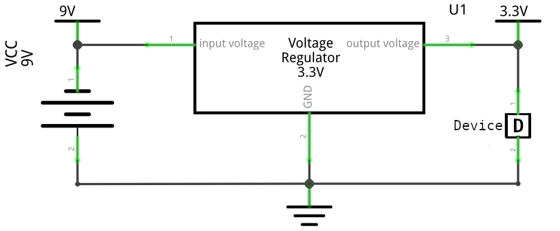
The figure below shows an exemplary circuit of a constant power supply of 9 volts (input voltage), a fixed voltage regulator producing a fixed DC output voltage of 3.3 volts, and an external device drawing 0.25 ampere:

Exemplary circuit of a constant power supply, a fixed voltage regulator, and an external device.

Based on the three input parameters VIN, VOUT, and IMAX, the regulator has to dissipate a peak power of 1.425 watts: (9V - 3.3V) * 0.25A

© 2024 Dr. Mountain

Theme von Anders NorénHoch ↑