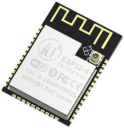
The ESP32-S from Ai-Thinker is a small-size, low-power wireless module for a wide variety of applications like a low-power sensor with a demanding task such as voice encoding. It is based on the famous ESP32 from Espressif, more precisely the ESP32-D0WDQ6 chip, designed to be scalable and adaptive. Please have a look at the following post for an in-detail description of the related features and specifications of the ESP32 chip (coming soon). The ESP32-S is Ai-Thinker’s equivalent to the ESP32-WROOM-32 module from Espressif, equaling in the form factor and specifications.
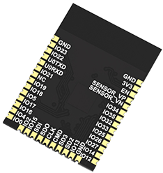
Pin Definitions
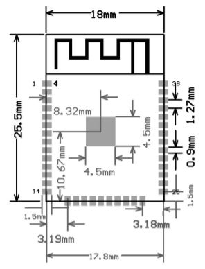
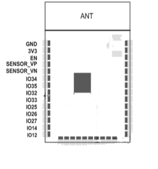
The ESP32-S has a length of 18 mm, a width of 25.5 mm and a height of 2.8 mm ∓ 0.1 mm. Furthermore, it has 38 pins, defined as follows (cf. Datasheet):
The following table shows the name, type, number and function of the pins on the left-side of the ESP32-S:
| Name | Type | GPIO | Function |
|---|---|---|---|
| GND | P | Ground | |
| 3V3 | P | Power Supply: 3.3V (VDD), 500 mA | |
| EN | I | Chip-enable Signal (Active high) | |
| SENSOR_VP | I | ADC_H, ADC1_CH0, RTC_GPIO0 | |
| SENSOR_VN | I | ADC1_CH3, ADC_H, RTC_GPIO3 | |
| IO34 | I | GPIO34 | ADC1_CH6, RTC_GPIO4 |
| IO35 | I | GPIO35 | ADC1_CH7, RTC_GPIO5 |
| IO32 | I/O | GPIO32 | XTAL_32K_P (32.768kHz crystal oscillator input), ADC1_CH4, TOUCH9, RTC_GPIO9 |
| IO33 | I/O | GPIO33 | XTAL_32K_N (32.768kHz crystal oscillator output), ADC1_CH5, TOUCH8, RTC_GPIO8 |
| IO25 | I/O | GPIO25 | DAC_1, ADC2_CH8, RTC_GPIO6, EMAC_RXD0 |
| IO26 | I/O | GPIO26 | DAC_2, ADC2_CH9, RTC_GPIO7, EMAC_RXD1 |
| IO27 | I/O | GPIO27 | ADC2_CH7, TOUCH7, RTC_GPIO17, EMAC_RX_DV |
| IO14 | I/O | GPIO14 | ADC2_CH6, TOUCH6, RTC_GPIO16, MTMS, HSPICLK, HS2_CLK, SD_CLK, EMAC_TXD2 |
| IO12 | I/O | GPIO12 | ADC2_CH5, TOUCH5, RTC_GPIO15, MTDI, HSPIQ, HS2_DATA2, SD_DATA2, EMAC_TXD3 |
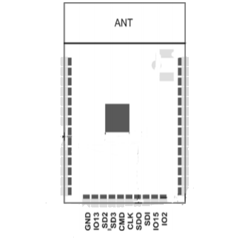
The following table shows the name, type, number and function of the pins on the bottom of the ESP32-S:
| Name | Type | GPIO | Function |
|---|---|---|---|
| GND | P | Ground | |
| IO13 | I/O | GPIO13 | ADC2_CH4, TOUCH4, RTC_GPIO14, MTCK, HSPID, HS2_DATA3, SD_DATA3, EMAC_RX_ER |
| SHD/SD2 | I/O | GPIO9 | SD_DATA2, SPIHD, HS1_DATA2, U1RXD |
| SWP/SD3 | I/O | GPIO10 | SD_DATA3, SPIWP, HS1_DATA3, U1TXD |
| SCS/CMD | I/O | GPIO11 | SD_CMD, SPICS0, HS1_CMD, U1RTS |
| SCK/CLK | I/O | GPIO6 | SD_CLK, SPICLK, HS1_CLK, U1CTS |
| SDO/SD0 | I/O | GPIO7 | SD_DATA0, SPIQ, HS1_DATA0, U2RTS |
| SDI/SD1 | I/O | GPIO8 | SD_DATA1, SPID, HS1_DATA1, U2CTS |
| IO15 | I/O | GPIO15 | ADC2_CH3, TOUCH3, MTDO, HSPICS0, RTC_GPIO13, HS2_CMD, SD_CMD, EMAC_RXD3 |
| IO2 | I/O | GPIO2 | ADC2_CH2, TOUCH2, RTC_GPIO12, HSPIWP, HS2_DATA0, SD_DATA0 |
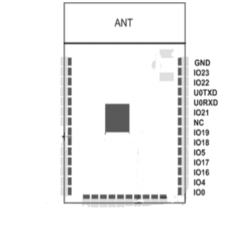
The following table shows the name, type, number and function of the pins on the right-side of the ESP32-S:
| Name | Type | GPIO | Function |
|---|---|---|---|
| IO0 | I/O | GPIO0 | ADC2_CH1, TOUCH1, RTC_GPIO11, CLK_OUT1, EMAC_TX_CLK |
| IO4 | I/O | GPIO4 | ADC2_CH0, TOUCH0, RTC_GPIO10, HSPIHD, HS2_DATA1, SD_DATA1, EMAC_TX_ER |
| IO16 | I/O | GPIO16 | HS1_DATA4, U2RXD, EMAC_CLK_OUT |
| IO17 | I/O | GPIO17 | HS1_DATA5, U2TXD, EMAC_CLK_OUT_180 |
| IO5 | I/O | GPIO5 | VSPICS0, HS1_DATA6, EMAC_RX_CLK |
| IO18 | I/O | GPIO18 | VSPICLK, HS1_DATA7 |
| IO19 | I/O | GPIO19 | VSPIQ, U0CTS, EMAC_TXD0 |
| NC | – | – | |
| IO21 | I/O | GPIO21 | VSPIHD, EMAC_TX_EN |
| RXD0 | I/O | GPIO3 | U0RXD, CLK_OUT2 |
| TXD0 | I/O | GPIO1 | U0TXD, CLK_OUT3, EMAC_RXD2 |
| IO22 | I/O | GPIO22 | VSPIWP, U0RTS, EMAC_TXD1 |
| IO23 | I/O | GPIO23 | VSPID, HS1_STROBE |
| GND | P | Ground |
Modules and Functions
(coming soon)
Electrical Characteristics
(coming soon)
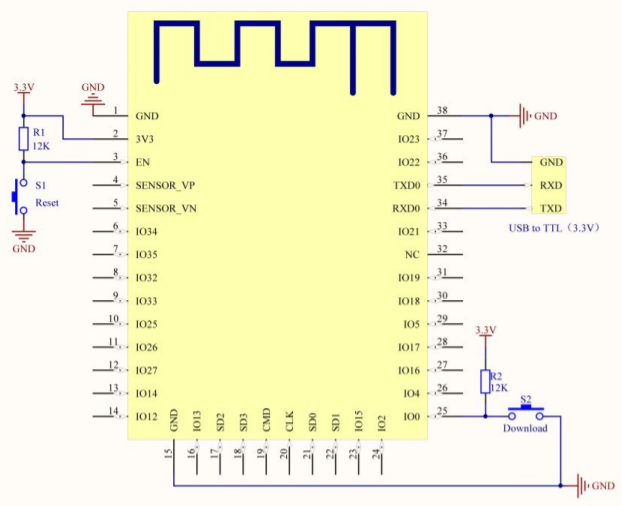
Schematic Diagram
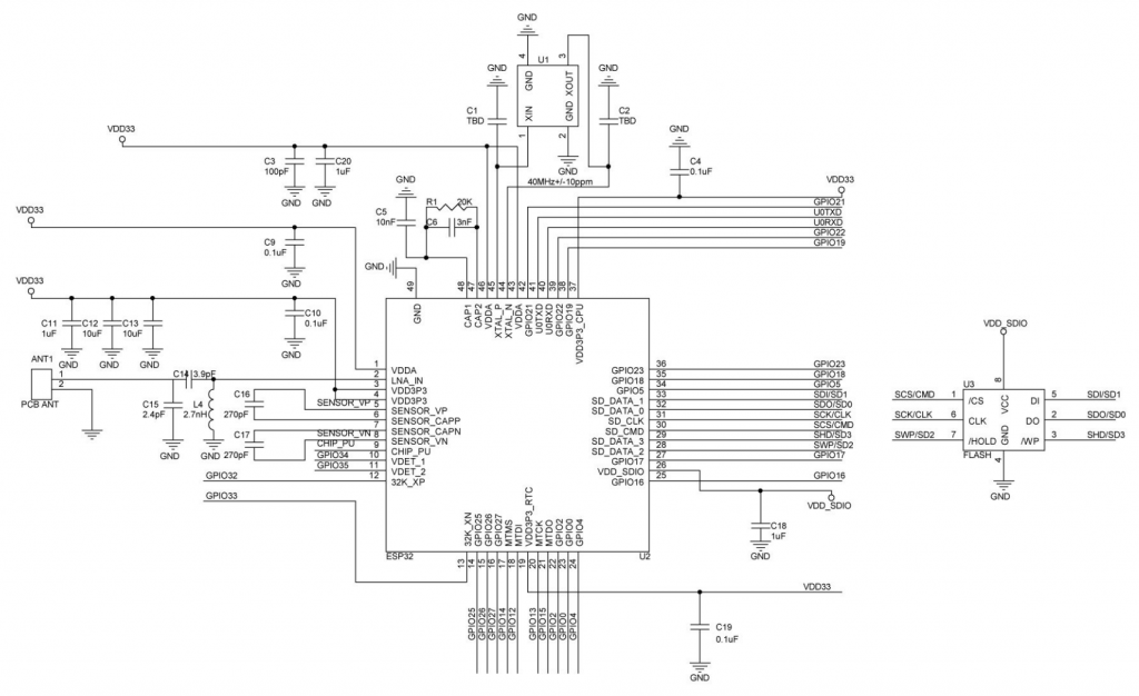
Neueste Kommentare