The Doc whom IoT Professionals trust

Schlagwort: ESP32-CAM

AMS1117-3.3: The Linear Voltage Regulator on the ESP32-CAM

Reading Time: 2 Minutes

The ESP32-CAM uses the fixed, linear voltage regulator AMS1117-3.3 from Advanced Monolithic Systems (AMS) that possesses a built-in protection against short circuit and thermal overloads:

ESP32-CAM w/ ASM1117 highlighted
AMS1117 SOT-223 Top View

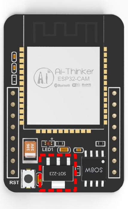
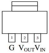
For instance, the circuitry-wise thermal protection will shut-down the linear regulator in case the junction temperature is above 165 °C at the sense point. It provides an output voltage of 3.3V by a maximum output current of 1.5A and a maximum input voltage of 15V. The AMS1117-3.3 guarantees a low dropout voltage (input-to-output differential: VDROPOUT = VIN – VOUT) of maximum 1.3V at the maximum output current of 1.5A. The dropout voltage decreases at lower load currents and operates down to 1V dropout voltage. The on-chip trimming develops a reference voltage of 1.25V between the output and the ground with a precise reference tolerance of 1.5%.

Electrical Characteristics

The table below shows the electrical characteristics of the AMS1117-3.3 at IOUT = 0 mA, and TJ = +25°C (unless specified otherwise):

ParameterConditionsMinTypMaxUnits
Reference VoltageIOUT = 10 mA
1.5 V ≤ (VIN – VOUT) ≤ 12 V
1.21251.2501.2875V
Output VoltageVIN = 4.8V3.2013.3003.399V
Line Regulation1.5V ≤ (VIN – VOUT) ≤ 12V1.010mV
Load RegulationVIN = 4.75V, 0 ≤ IOUT ≤ 0.8A725mV
Dropout Voltage∆VOUT, ∆VREF = 1%, IOUT = 0.8A1.11.3V
Current Limit(VIN – VOUT) = 1.5V90011001500mA
Minimum Load
Current
(VIN – VOUT) = 1.5V510mA
Quiescent Current(VIN – VOUT) = 1.5V511mA
Cf. data sheet of the AMS1117

Using the SD Card in 1-Bit Mode on the ESP32-CAM from AI-Thinker

Reading Time: 2 Minutes

The ESP32-CAM from AI-Thinker has an on-board connector for micro SD cards:

ESP32 CAM Front-View
Front View (Source)
ESP32 CAM Back-View
Back View (Source)

The ESP32 connects to an SD card via the SDMMC Host Driver, more precisely via slot 1. It is a 4-bit slot and uses the HS2_* signals in the PIN MUX. The following table shows the pin and signal mappings (cf. schematic diagram):

SignalGPIOComment
HS2_CMDGPIO15Exposed
HS2_CLKGPIO14Exposed
HS2_DATA0GPIO02Exposed
HS2_DATA1GPIO04Exposed and also connected to on-board SMD LED
HS2_DATA2GPIO12Exposed
HS2_DATA3GPIO13Exposed
Pin mapping of slot 1 of the ESP32’s SDMMC host peripheral

As shown above, the ESP32-CAM uses the GPIO pins GPIO02, GPIO04, GPIO13 and GPIO15 for reading and writing data to the SD card. To use the SD card in the ‚1-Bit‘ or ‚1-Wire‘ mode, just initialize the SD card with the following code (cf. Espressif Arduino core for the ESP32):

bool begin(const char * mountpoint="/sdcard", bool mode1bit=false); // cf. SD_MMC.h
SD_MMC.begin("/sdcard", true);

By setting the parameter mode1bit to true, the ESP32-CAM just uses the GPIO02 to read and write data to the SD card, which frees up the GPIO pins GPIO04 (HS_DATA1), GPIO12 (HS_DATA2), and GPIO13 (HS_DATA3) as further GPIO pins for input or output. To use one or all of these GPIO pins for input or output, you have to define the GPIO pin accordingly after the initialization of the SD card. Otherwise, the initialization of the SD card would re-configure the GPIO pins again. For instance, the following code snippet configures the GPIO pin GPIO12 as an output pin and sets it to low:

pinMode(12, OUTPUT);
digitalWrite(4, LOW);

Please note that the ESP32-CAM uses the GPIO04 to connect to the on-board flash light as well – the SMD (Surface-Mount Device) LED (Light-Emitting Diode). To prevent the SMD LED from glowing, use the following code:

#include "SD_MMC.h"
#include "SPI.h"

#define BUILTIN_LED 4

void setup() {
    Serial.begin(115200);

    // Initialize the SD card
    if (!SD_MMC.begin("/sdcard", true)){
        Serial.println("Failed to mount SD card");
        return;
    }

    // Specify that LED pin
    pinMode(BUILTIN_LED, OUTPUT);
    digitalWrite(BUILTIN_LED, LOW);

    // Check for an SD card
    uint8_t cardType = SD_MMC.cardType();
    if (cardType == CARD_NONE){
        Serial.println("No SD card attached");
        return;
    }

    // <Put your init code here>
}


void loop() {
  // <Put your main code here, to run repeatedly>
  Serial.println("loop end, 10sec delay");
  delay(10000);
}

© 2024 Dr. Mountain

Theme von Anders NorénHoch ↑